Monday, September 29, 2014

One Point Oh

Nigel and I are pleased to announce that version 1.00 of the retro-B5500 emulator was released on 29 September 2014. All changes have been posted to the Subversion repository for our Google Code project GitHub project. The hosting site has also been updated with this release, and for those of you running your own web server, a zip file of the source can be downloaded from the GitHub repository [updated 2022-05-07].

This release is a significant milestone in the development of the emulator. We have bumped the release level from 0.20 to 1.00 as we feel the emulator is now functionally complete. It is not finished, of course, and probably never will be. There are features of the B5500 that we still do not support (e.g., drums and paper tape devices), areas where significant improvements can be made (e.g., multiple datacom stations), and some areas that may not be practical to support in a browser-based emulator (e.g., File Protect Memory, shared disk systems, and additional datacom line-adapter types). Those issues can be pursued as our time and the desire of the user community permit.

This is also a very large release, with many new features and changes to existing ones. This blog post will attempt to introduce and summarize these changes, but there have been extensive updates to the wiki pages as well. The wiki now also has a table of contents, which can be displayed as a sidebar on the left of the wiki pages. We recommend that before using this new release, you peruse the following wiki pages in particular:

New System Configuration Mechanism


The most significant feature of this release is a completely new, and much more flexible configuration mechanism for the emulator.

Overview


In earlier releases, the system configuration was defined by a static Javascript file, emulator/B5500SystemConfiguration.js. If you were running your own web server, you could modify this file to alter the system configuration -- the processors, memory modules, I/O control units, and peripheral devices the emulator would use. If you were using the emulator from a web server hosted by someone else, however, you were stuck with whatever configuration was coded in the Javascript file on that server.

An additional restriction in earlier releases was that the configuration of the disk subsystem was fixed by the B5500ColdLoader.html script and could not be changed. The standard script created a disk subsystem with two Electronics Units (EUs) having a total of 400,000 sectors, or 96 million 6-bit characters of storage.

The new mechanism stores the system configuration in a small IndexedDB database within your browser. There is a new user interface (UI) that allows you to select the system components you want to make up a configuration. Since this data is stored locally on your workstation, each user can control their own configuration, even when the emulator files are hosted on an external web server. The Javascript file still exists, but its role is now to define the structure of the system configuration data. It is no longer used by the running emulator.

You can now also define multiple configurations and easily switch among them. Each configuration has a name that identifies it within the IndexedDB database. There is no practical limit to the number of configurations you can create. Switching between configurations is as easy as opening the configuration UI and selecting the desired name from a pull-down list.

In addition, the new configuration mechanism supports multiple disk subsystems. Each disk subsystem is implemented as a separate IndexedDB database within the browser. There are a number of uses for multiple disk subsystems. One is to support separate systems for the Datacom and Timesharing MCPs. Another is to maintain different levels of the MCP and easily switch among them.

You can specify the number of EUs in a disk subsystem and the number of Storage Units (SUs) independently for each EU. You can also modify the configuration of a subsystem at a later time to add more EUs or add more SUs to existing EUs. A disk subsystem can have up to 20 EUs (the B5500 maximum), although only the first ten EUs are addressable when the system configuration includes a Disk File Exchange (DFX) component.

The emulator now supports both the original Model-I SUs (40,000 sectors, 20ms average access time) and Model-IB SUs (80,000 sectors, 40ms average access time). The latter model was known as "bulk" or "slow" disk. All SUs for an EU must be the same model, but separate EUs can have different SU models.

You assign a name to each disk subsystem when you create it. That name also becomes the name of the subsystem's IndexedDB database. You use this name to assign the subsystem to a system configuration. A given system configuration can have only one disk subsystem associated with it at a time, but the subsystem associated with a system configuration can be changed at any time.

Using the New Configuration Interface


The emulator permits configuration changes to be made only when it is in a powered-off state. To access the configuration UI, simply click the "B5500" logo (below the Burroughs logo) on the right side of the Operator Console window. A System Configuration sub-window will open:

Emulator System Configuration Dialog

To change the set of components in a configuration, simply tick or un-tick the appropriate check boxes on the dialog and click the SAVE button. To switch to a different configuration, select it from the Configuration name list and click SAVE. To create a new system configuration, click the NEW button. The dialog will prompt you for the name of the new configuration and then fill the dialog with a default configuration, which you can modify as desired. Each time you click the SAVE button, the displayed configuration becomes the "current" configuration for the emulator. That will be the one used the next time the emulator is powered-on.

To delete a configuration, select its name from the pull-down list and click the DELETE button. The dialog will prompt you for confirmation of the delete, but once acknowledged, the deletion is permanent and cannot be undone.

Note that some elements on this dialog represent features that are not presently supported by the emulator. Their controls are disabled on the dialog.

You assign a disk subsystem to a system configuration by selecting the subsystem name from the Storage name pull-down list on the dialog. Saving the configuration associates that subsystem with that configuration. You can create or modify a disk subsystem by clicking the NEW or EDIT buttons next to the list of storage names. Doing so will open the Disk Storage Configuration dialog in a new sub-window:

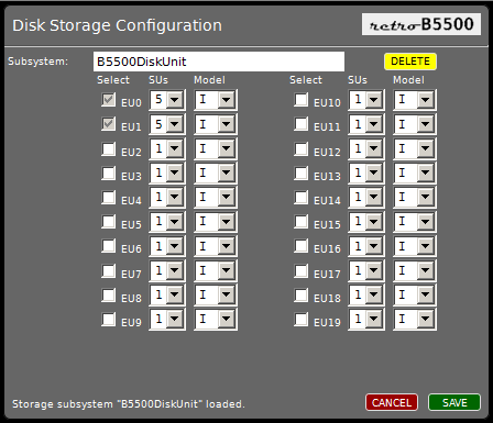
Disk Storage Configuration Dialog


If you click the NEW button, the system configuration dialog will prompt you for the name of the new disk subsystem before opening the storage configuration dialog. To add EUs to the subsystem, simply tick their check boxes and select the number and model of SUs the EU should have. Click the SAVE button on this dialog to update the configuration, apply any necessary schema changes to the IndexedDB database, and associate this subsystem with the underlying system configuration.

Once you click SAVE, any storage you have added to the subsystem becomes a permanent part of the subsystem and cannot be removed later. The check boxes for the selected EUs will be disabled so that they cannot be un-ticked. You may not decrease the number of SUs, nor change Model-IB SUs to Model-I SUs, as either of those changes would reduce the amount of storage in the subsystem.

The reason for the restriction on removing storage from a subsystem is that the B5500 MCP considers all disk on the system to be a monolithic resource. Disk files are organized as a set of separately-allocated areas (extents), which may be spread across multiple EUs of the subsystem. Removing storage from the subsystem could cause some areas of files to disappear, so the emulator does not allow this.

To delete a disk subsystem, open it in the Storage Configuration dialog and click the DELETE button. The dialog will prompt you for confirmation, but once acknowledged, the IndexedDB database for the subsystem will be deleted from your workstation. This deletion cannot be undone.

Disk subsystems from earlier emulator releases can be used without change in 1.00 and later releases. These legacy subsystems have the name B5500DiskUnit. The legacy subsystems can continue to be used with earlier releases of the emulator if their configuration is not changed. Once you change the configuration of a disk subsystem, however, it can no longer be used by releases prior to 1.00. There two reasons for this:
  • Adding EUs to a disk subsystem requires a change to the IndexedDB database schema. This change increases the IndexedDB version property for the database. Releases prior to 1.00 required the database to be at version 1 and will not open a database having a higher version.
  • Each IndexedDB database for a disk subsystem contains a configuration table that describes the EUs in the subsystem. The format of that configuration table has changed for release 1.00 in a way that is incompatible with earlier releases. This also means that disk subsystems created by release 1.00 and later cannot be used with earlier emulator releases, even it their IndexedDB version is 1.

Updating from Earlier Releases


When you first power-on the 1.00 emulator in a browser with which the emulator was previously used, the emulator will create a default system configuration named "Default", having a set of components that is somewhat reduced from the default configuration in earlier releases. In particular, it has only one Disk File Control Unit (DKA) and one magnetic tape drive. The configuration will include any existing legacy B5500DiskUnit subsystem. You may wish to adjust this default configuration before proceeding further.

When you first power-on the 1.00 emulator in a browser where the emulator has not been previously used, the emulator will create both the default system configuration described above and a default disk subsystem named B5500DiskUnit. That configuration will have half the storage of previous default configurations -- one EU with 200,000 sectors, or 48 million characters.

Please see the Configuring the System wiki page for more details on the new configuration mechanism and how to use it.


New Cold Start Process


With the implementation of the new system configuration mechanism in this release, use of the B5500ColdLoader.html script is now deprecated. That script served to create the IndexedDB disk subsystem, initialize the disk directory structures, establish the bootstrap mechanism, and load the MCP and other system files from ".bcd" tape images. It dates from a very early point in the emulator development, long before card reader and magnetic tape peripheral devices were implemented.

We now recommend that disk subsystems be created using the new system configuration mechanism, and that they be initialized the old-fashioned way -- with a Cold Start card deck.

We have actually been able to Cold Start the system from a card deck for almost a year, ever since the initial tape drive implementation was made available in release 0.15 last November. We owe thanks to Tim Sirianni and Paul Cumberworth for pioneering the research in how to do this, using the ESPOL compiler to generate the necessary card-load decks from relevant symbol files, and assembling the decks with an appropriate set of parameter cards.

I have taken Tim's latest version of his deck, reworked the parameter cards somewhat, and created a default Cold Start deck you can load directly, or use as a base for customization. This deck is in the tools/ directory of the emulator files, and can also be downloaded from our hosting site at http://www.phkimpel.us/B5500/tools/COLDSTART-XIII.card.

The Cold Start deck consists of two "card-load-select" programs, the COLD Loader and Tape-to-Disk Loader, along with their respective control cards. At the end of the deck is a short MCP Library/Maintenance job that will load a minimal set of system files from the Mark-XIII SYSTEM tape image to disk.

To use the Cold Start deck, follow these steps:
  1. First download a copy of the deck to your local file system.
  2. If you wish, you can modify the parameter cards to suit your preferences, but be careful not to disturb the card images for the card-load programs themselves. Many of the settings on the parameter cards can be modified using SPO commands after the MCP is up and running, so you may want to leave the deck as is, at least initially.
  3. Load the emulator into your browser. Make sure you have the correct system configuration and disk subsystem selected. A Cold Start wipes out any existing disk directory on the disk subsystem, effectively destroying all B5500 files in the subsystem.
  4. Power-on the emulator.
  5. Load the Cold Start deck into card reader CRA and press the START button on the reader.
  6. Load the SYSTEM tape image into a tape drive (any available drive will do) and click the drive's REMOTE button to make it ready.
  7. On the Operator Console, click the yellow CARD LOAD SELECT button so that it illuminates.
  8. Click the LOAD button on the Console. The reader will load the one-card binary bootstrap on the front of the deck, which will then load the COLD Loader program into memory and start executing it. The COLD Loader will initialize the disk subsystem and create an empty disk directory. It will also process the parameter cards and store their values on disk. The program will then print "DIRECTRY BUILT" [sic] on the SPO and halt. The process should take about 30 seconds.
  9. Leave the CARD LOAD SELECT button illuminated. Click the HALT button, then click LOAD again. The reader will load another one-card binary bootstrap, which will in turn load the Tape-to-Disk Loader program and start executing it. You should see the tape spin as the loader searches for the MCP file and loads it to disk. After a successful load, the program will print "MCP FILE LOADED" on the SPO. It will then automatically boot the MCP just loaded.
  10. The standard parameter cards for the COLD Loader will set an MCP option that requires you to set the time of day after a halt/load. You should first set the date with the SPO DR command. Then once you set the time with a TR command, the MCP will read the cards for the Library/Maintenance job and load those files to disk.
  11. One of the files that job loads is the System Intrinsics, INT/DISK. Since the system was just Cold Started, you must specify the name of the Intrinsics file to the MCP using the SPO command "CI INT/DISK". The MCP will preserve that setting across future halt/loads.
  12. At this point the system is fully initialized and ready for use. You may wish to load additional files from the SYSTEM tape, or wait and load more files later as the need arises. It would be a good idea to click the CARD LOAD SELECT button at this time to turn it off.

The B5500ColdLoader.html script can still be used to initialize a disk subsystem for use with release 1.00, but it can only work with the disk subsystem named B5500DiskUnit in its legacy configuration. This script will be removed in a future release, so we strongly recommend that you stop using that script and switch to the new process described above.

Please see the Getting Started wiki page for more details on how to initialize the emulator environment using the new configuration mechanism and Cold Start card deck. That page also has links to the B5500 reference manuals that describe the card-load-select programs and their parameter cards.


Off-line Emulator Operation and the "Application Cache"


The emulator, like most non-trivial web applications, cannot be loaded into a browser from your local file system. Instead, it must be loaded over HTTP from a web server. Once loaded, however, the emulator runs completely within the browser, and the web server is not needed again until the next time you load or reload the emulator.

The continually-evolving HTML5 standards have established a browser feature known as the "Application Cache." This is a bit of a misnomer, as it is not so much a cache as it is a way to install a web application within a browser for off-line use. Once the application is installed, it can be run in the browser without access to the web server from which it is hosted, and even without the browser having access to a network connection at all. Both Google Chrome and Mozilla Firefox support this capability.

Not all web applications can take advantage of off-line operation, especially if they require access to Internet resources while they are running. It is perfectly suited to the emulator, however, since the emulator requires no network or Internet access once it is loaded into the browser. Thus, it is now possible to use a version of the emulator that is hosted on an external web server in situations where you have no access to that server. You load the emulator into the browser using the same URL you would if operating on-line, but the browser will load the emulator files from its local Application Cache rather than from the web server.

Installation and use of the emulator from the Application Cache is unconditional and completely automatic. The first time you load the emulator using release 1.00 or later, the browser will load the emulator files into its local storage. You will see messages displayed in the top-left of the Operator Console window as the application is installed and the complete set of emulator files is downloaded.

Once the emulator is installed within your browser in this way, it will continue to be served from the local Application Cache, even when your browser has network access and can reach the web server from which the emulator was originally hosted. Instead of loading the emulator files from the server when on-line, the browser will instead check the server to see if a newer version of the emulator is available. This check takes place asynchronously, in the background, and neither inhibits nor delays use of the emulator while it is taking place. You will see some messages display in the top-left of the Console while this check takes place.

If a newer version of the emulator is available on the server, the browser will download it, again asynchronously in the background. The new version will be installed automatically in the Application Cache, but the browser will continue to use the prior version until the next time the emulator is reloaded in the browser. At that point the new version of the emulator will be used by the browser and the prior version will no longer be available. This behavior is not unlike the way that most web browsers themselves are updated automatically from the Internet and made available the next time you restart them on your workstation.

Please see the Using the Operator Console wiki page for more details on off-line operation of the emulator and the messages that are displayed during the application installation and update process.


Peripheral I/O Device Changes


This release contains numerous changes and enhancements to the I/O devices and their user interfaces. The following discussion summarizes the differences from prior releases, but please see the respective wiki page on each device for details.

Line Printer


The line printer driver has been completely rewritten. The original driver was a quick-and-dirty implementation, literally thrown together as a debugging exercise. It worked well enough that we have continued to use it, but it had no operating controls and was missing several important features.

The new driver supports a user interface with controls similar to those of the B329 printer. There are now buttons to make the printer ready and not ready, and to manually perform single-space and form-feed operations. To keep printed output from flooding the memory of the browser, the printer has long limited the capacity of its "paper" area to 150,000 lines -- about the equivalent of a box of the pin-feed forms used with the real printers. The new driver now supports an end-of-paper indicator and a more realistic way of clearing the "paper" from the printer when its capacity is reached.

The B5500 used five special Algol characters that do not have ASCII equivalents -- left-arrow, multiplication, not-equal, less-than-or-equal, and greater-than-or-equal. As described in the wiki pages, we have assigned ASCII substitutes for these (e.g., left-arrow as "~"), but several people have expressed a desire to see the actual Algol glyphs, especially in printer output.

The Unicode standard has glyphs for all five special Algol characters, and many fonts available for workstation operating systems include these glyphs. The new line printer driver will now generate these Unicode glyphs, but an option on the printer UI allows you to turn this off and still obtain printed output with the ASCII substitute characters. The default setting for that option can be specified in the system configuration.

Card Reader


The card reader will now unconditionally accept the five Unicode code points for the special Algol characters in "deck" files that are loaded into it. Files may contain a mixture of both Unicode and the ASCII substitutions for the Algol characters. The reader will now also accept the underscore ("_") as an ASCII substitute for the left-arrow.

Card Punch


Similar to the new line-printer driver, the card punch will now optionally output the five special Algol characters using Unicode glyphs. The default setting for that option is also in the system configuration.

The card punch UI now has annunciators on the right side of its panel that will illuminate when one of the output stackers reaches its capacity of 850 cards.

SPO


The SPO interface has been redesigned to accept keyboard input using a standard HTML text box. Formerly, keystrokes were simply captured by the driver when the SPO window or its paper area had the focus. This works fine when you have a real keyboard, but not at all on mobile devices such as tablets that simulate a keyboard on their touch surface. Most of these devices only display the simulated keyboard in a browser when the focus is in a text box or other control that accepts text input. Since the original SPO did not use a text control, there was no way to get the keyboard to appear.

In the new implementation, the SPO driver will enable a border-less, yellow-shaded text box at the bottom of the paper area whenever an I/O Control Unit issues a read operation to the SPO. The MCP initiates a SPO read in response to you clicking the INPUT REQUEST button on the SPO window, or pressing the ESC key when the SPO window has the focus. This text box is disabled and made invisible when you end input to the SPO.

This new approach has solved several obscure, but long-standing problems with input to the SPO. It also has the advantage that you now see a cursor when keying text on the SPO, and you can use standard GUI editing and copy/paste operations during SPO input. It seems to work fine on the tablets we have tested. There are still numerous issues with running the emulator on a mobile device, however (e.g., the I/O devices open as tabs instead of windows), but we have seen significant improvement during the past few months in the ability of mobile devices to support the emulator, particularly with Google Chrome on Android devices.

As a part of the changes to implement the new text input mechanism, the paper area of the SPO is no longer implemented as an HTML <iframe> element. You can still select and copy portions of the SPO output with your pointing device, but as a consequence of this change, it is no longer possible to save or print the contents of the paper area directly from your browser. To help compensate for this, double-clicking anywhere in the paper area will cause a new window to be opened and the current contents of the paper area copied into it. You can then save or print the SPO output from this separate window. Simply close the window when you are finished with it.

The amount of scroll-back retained by the SPO remains at 1500 lines. Older lines are discarded once this limit is reached.

Additional enhancements to the SPO include:
  • Support for the Unicode Algol Glyphs on output has been implemented in a manner similar to that for the line printer and card punch. Unicode code points on input are not currently supported, however.
  • The underscore ("_") is now accepted as a substitute for "~" on input. Keying either of these characters acts as if the END OF MESSAGE button had been clicked.
  • When you resize the SPO window, the paper area will resize in concert. This is especially useful when running the emulator on a workstation with a relatively small screen. Below a certain minimum size, however, the paper area will no longer resize and the contents of the window will be clipped. The really interesting thing to me about this feature is that it was implemented entirely through CSS style sheet changes. No Javascript was harmed in the process.

Magnetic Tape


The tape loader window that is activated by clicking the LOAD button for a tape drive is now opened on top of the drive window. Previously it was opened in the center of the workstation screen, which could make it confusing to which drive the loader window applied.

Timing for the animation of the tape reel image on the drive window is now done at a more granular level. This should improve the quality of the animation and reduce the degree of visual beating between the simulated rotation of the reel and the screen refresh rate.

Disk


Disk devices do not have a user interface, but there have been a few significant improvements internally.
  • The driver has been updated to work with the new system configuration and disk subsystem mechanism. It now attaches to the IndexedDB database for the disk subsystem specified by the current system configuration and adapts to the configuration of that subsystem. 
  • The driver now supports Model-IB (slow) disks in addition to the original Model-I disks, including the difference in average access time.
  • The driver now supports both configurations with a Disk File Exchange (DFX) and those without a DFX. Without a DFX, the B5500 supports up to 20 EUs, with EU0-9 addressed by DKA and EU10-19 addressed by DKB. With the DFX enabled, the system can support only EU0-9, but both disk controls can address any disk.
  • The emulator will now refuse to do a disk load if DKA is not selected in the system configuration. This mimics the way the B5500 hardware worked.

Datacom


The way that keyboard input for the datacom terminal was handled has been extensively reworked for better compatibility with Google Chrome. A more tablet-friendly input mechanism, similar to that described above for the SPO, is under consideration, but it is much more difficult to implement for a datacom terminal, as the input mode is initiated by the user pressing any key, not by the I/O Control Unit.

General Improvements


In earlier releases, the NOT READY indicators on the I/O device windows were rendered in red. Closer inspection of some color photographs of actual B5500 installations has revealed that this is incorrect -- the lamps were white. All I/O device windows have been updated to reflect this.

Several device windows have progress bars on them to indicate things such as input or output capacity. These were being rendered with HTML <progress> elements, but this usage is an incorrect application of that type of element. These have been converted to <meter> elements, which are visually very similar.

As with the resizing feature for the SPO, most other device drivers now resize their widow contents when their windows are resized.

Other Changes and Enhancements


Flag Bit Errors


For some time we have had a problem with programs aborting due to Flag Bit interrupts. These typically occur during periods of intense system activity, which suggests the problem may be related to Presence Bit interrupts. It has been a difficult problem to track down.

More or less by accident, I discovered a bug in the Processor object, where the stack was not being properly adjusted during the indexing of a descriptor. The value of the A register was being used without assuring first that the AROF validity flip-flop was set. As part of that, I also reworked portions of the OPDC and DESC operators in the area that detects Flag Bit errors.

Improper stack adjustment could lead to Flag Bit errors. These changes appear to have reduced the incidence of Flag Bit errors when the system is very busy, but they still occur occasionally. The most recent cases I've examined appear to happen during procedure exit, where the processor is checking the Flag Bit [0:1] on the Return Control Word. This is the only known bug in the Processor at present, and remains an outstanding issue (#23 in the project's issue list).

Downloadable Web Fonts


Normally, web browsers render the contents of their windows using fonts that are installed locally on the workstation. Browsers have for some time supported downloadable fonts, however, so we have taken advantage of that feature in this release. The intent is to standardize the fonts used by the emulator, and to eliminate any dependency on fonts installed locally on the workstation.

We have chosen the open-source DejaVu Sans and DejaVu Sans Mono fonts for use with the emulator. The Mono font was specifically chosen because it supports the Unicode glyphs for the special Algol characters, and because it has a numeric "0" glyph that is clearly distinguished from the letter "O".

This release includes files for these two fonts in both Web Font (.woff) and TrueType (.ttf) formats. The font files are quite large, but due to their local storage by the Application Cache feature discussed above, and the fact that they never change, you should be burdened by their download only once.

Operator Console Improvements


Prior to this release the NOT READY lamp on the Console was not implemented. When the emulator is powered-on, this lamp will now be illuminated if certain minimum configuration requirements are not met, e.g., no Processor is enabled in the configuration, the selection for P1 (the control processor) is not valid, or memory module 0 is not enabled. This is not exactly how that lamp behaved on the B5500, but the current implementation follows its purpose in spirit.

In previous releases, clicking the NOT READY lamp would toggle Processor B into or out of the running configuration. That was always intended as a temporary feature, and it has been removed in this release. The presence of PB can now be controlled through the new system configuration mechanism.

The Console will now perform a brief lamp test when the POWER ON button is clicked. Please report any burned out lamps on the forum.

The names of the current system configuration and disk subsystem are now displayed in the top-right of the Console window when the Console is in "non-purist" mode. Clicking the Burroughs logo toggles the Console between the historically-accurate "purist" mode and the default "non-purist" mode, which shows additional legends and annunciators for system status.

Miscellaneous Changes


Many of the scripts and style sheets have been significantly cleaned up and refactored. The user interface now has a more standardized appearance, and this will be easier to maintain going forward.

Images and fonts have been moved into a new webUI/resources/ directory to separate them from the HTML, CSS and Javascript files in webUI/. A number of files in the webUI/tool/, tools/, tests/, and source/ directories have been moved to more logical locations within the project's Subversion repository.

All HTML <meta> Content-Type character sets have been changed from ISO-8859-1 to UTF-8 so that the Unicode glyphs could be supported. A problem with FireFox requiring the character set to be specified within the first 1024 characters of an HTML file has been corrected.

Looking Forward


We have a few ideas for further enhancements in the emulator, but none of them is particularly urgent. Of course, it is likely that we will uncover more bugs that will need to be corrected, but except for the problem with occasional Flag Bit errors, the emulator at present seems to be quite robust and reliable.

The focus on future work is likely to be acquisition and restoration of more software for the B5500. We already have quite a bit that exists in the form of scanned listings. Those need to be transcribed, proofed, and debugged in order to make them useful. That is a very labor-intensive and frustrating process, but Jim Fehlinger has made amazing progress in the past several months with an OCR-based technique that has improved the throughput and reliability of the transcription process substantially, although it is still quite labor-intensive.

Development of the emulator itself has been a closely-held project, but restoration of software is something in which anyone (and everyone) can easily participate. Nigel and I have been pleasantly surprised by the amount of interest this project has garnered, especially given that we have not done all that much to advertise it. We hope that people will continue to be interested in and volunteer to work towards the restoration of software for this very interesting system.

The 50th anniversary of first customer shipment of the B5500 will occur in February 2015. There needs to be a party.

Wednesday, July 9, 2014

Double Trouble: Version 0.20 Released

Nigel and I are pleased to announce that version 0.20 of the retro-B5500 emulator was released on 29 June. All changes have been posted to the Subversion repository for our Google Code project GitHub project. The hosting site has also been updated with this release, and for those of you running your own web server, a zip file of the source can be downloaded from the GitHub repository [updated 2022-05-07].

It has been five months since the previous version, 0.19, was released. That is far longer than any of us would have liked, but the main item in this release proved to be quite a challenge, as the following discussion will detail.


Double-Precision Arithmetic

The major enhancement in this release, and one that has been a long time coming, is a full implementation of the double-precision (DP) arithmetic operators, DLA, DLS, DLM, and DLD. These were the last operators left to be implemented in the Processor component of the emulator. Since the earliest releases they have been stubbed out by their single-precision (SP) equivalents, although a preliminary (and not very good) implementation of DP Add/Subtract has been available for more than a year.

There is actually one more operator that remains incompletely implemented, Initiate for Test (IFT, octal 5111). This is a diagnostic operator, and is available only in Control State. On the B5500, this operator had the ability to inject arbitrary state into the processor registers and initiate execution in the middle of an instruction. We do not emulate the B5500 at the clock level, however, and in particular we do not support the J register, which was used as a state variable to control stepping through execution of an instruction. Thus, we can't completely implement the IFT operator.

Coming into this project, I had suspected that the arithmetic operators were going to be difficult. In fact, I tried to hand them off to Nigel, but he was smart enough to hand them back. The SP operators were indeed a challenge, but that part of the instruction set proved to be very interesting to work on. If nothing else, I finally understood how long division works.

After getting the SP operators to work, I started to look at the DP operators, thinking they would be a straightforward extension of their SP equivalents. Oh, my... reading about the DP operators in the B2581 Processor Training Manual revealed that they were much, much more complex. In fact, they were downright intimidating. To understand why, we first need to look at how arithmetic is done in the B5500.

An Overview of Single Precision


The B5500 has a 48-bit word. That word can hold a single-precision numeric operand, or eight 6-bit characters, or a variety of control words. A SP numeric operand looks like this:

B5500 Single-precision Word Format
The high-order bit, numbered 0, is the flag bit, which is zero for operands and one for control words. Attempting to access a word as an operand in Word Mode that has its flag bit set will cause a (typically fatal) Flag Bit interrupt. In this sense the B5500 is a tagged-word architecture, but having the tag inside the word is quite awkward for processing character data -- when the high-order character has its high-order bit set and the processor is in Word Mode, it looks like a control word. Thus, character processing is normally done in Character Mode, which is not sensitive to the flag bit -- a characteristic that has its own set of problems. This awkwardness was resolved in the B6500 and later systems by expanding the tag and moving it to a separate field outside the 48-bit data portion of the word. In addition, character operations in the B6500 were combined with word operations into a single mode of processor operation.

Bit 1 is the sign of the mantissa, with a one indicating negative values. This is a signed-magnitude representation, so both positive and negative zero values are possible, although the arithmetic operators do not produce negative-zero results.

Bit 2 is the sign of the exponent, which also has a signed-magnitude representation.

The next six bits are the magnitude of the exponent, which is a power of eight. Therefore, when normalizing or scaling a floating-point value, the mantissa is shifted in three-bit groups, or octades.

The low-order 39 bits in the word are the mantissa. This size yields a precision of approximately 11.5 decimal digits.

With the exception of the flag bit, this looks like a fairly typical floating-point representation of the time, but there are two unusual things about it. The first is that the scaling point for the mantissa is not at the high-order end of the field, but rather at the low-order end. Unlike most floating-point representations that store the mantissa as a fraction, the B5500 represents its mantissa as an integer.

This leads to the second unusual characteristic. Not only is this the format of a floating-point operand, it is also the format for an integer operand. The B5500 has what is sometimes referred to as a unified numeric format. Integers are considered to be a subset of floating-point values, distinguished by having an exponent of zero. Most of the arithmetic operators attempt to keep the result of integer operands as an integer, but will automatically switch to a floating-point representation if the result overflows the integer range. Some floating-point results are not completely normalized, but that does not detract from their use in later calculations.

The idea for this unified format came either from the Bendix G-20 or the fertile mind of Bob Barton, depending on whose version of events you choose to believe. See the 1985 B5000 Oral History transcription for the story. The details of the formats for the two machines differ quite a bit, but the connection with the G-20 is plausible, as its predecessor, the G-15, was designed by Harry Huskey, who also consulted with Electrodata/Burroughs in the 1950s.

One consequence of this form of numeric representation is that you do not need separate instructions for integer and floating-point operations. To the hardware, there is no operational difference between 1 and 1.0, so a second consequence is that integer and floating operands can be mixed arbitrarily. A third consequence is that most integer values can be stored in multiple forms. For example, the value +1 has multiple representations, each with a different exponent value. The two most common are the one normalized as an integer [octal 0000000000000001], and the one fully-normalized as a floating-point value [octal 1141000000000000, i.e., (1×812) × (8-12)].

Doing arithmetic on mixed integer and floating-point values seems as if it might be quite complex, but its implementation on the B5500 is actually simpler than you may expect. The mechanization of the arithmetic operators is quite clever, and is discussed with headache-inducing detail in the Training Manual cited above. Here is a quick overview:
  • Addition and subtraction require that the exponents be equal. If both operands are in integer form, their exponents are zero, and therefore can simply be added or subtracted. If the exponents are unequal, the value with the larger exponent is normalized (shifted left with a decrease in exponent, if not already fully normalized) and the value with the smaller exponent is scaled (shifted right with an increase in exponent) until the exponents match or one of the mantissas goes to zero. If adding two integers yields a value that exceeds 39 bits, the result is automatically scaled, producing a floating-point result, with consequent loss of one octade of precision. A flip-flop keeps track of octades scaled off the low-order end of the word so the result can be rounded.
  • Multiplication notes whether both operands are initially in integer form, and if so, tries to produce an integer result, automatically overflowing to floating-point as necessary. Otherwise both operands are fully normalized before being multiplied.
  • Standard division, following the rules of Algol, always produces a real (floating-point) result, even with integer operands, and thus always normalizes its operands before commencing the division.
  • Integer division always normalizes its operands, but is mechanized in such a way as to produce either an integer result or an Integer Overflow interrupt.
  • Remainder division always normalizes its operands, and curiously, always produces a result in floating-point form. 5 mod 3 yields 2.0 in fully-normalized floating-point form. 3.3 mod 2 yields 1.3, or as close to it as you can represent with a binary fraction.
Variants of the store operators can normalize operands to integer representation when the semantics of the programming language require such. Fractional values are rounded during integerization. Attempting to integerize a single-precision value whose magnitude exceeds 39 bits results in an Integer Overflow interrupt.

Extending to Double Precision


So much for the single-precision representation and basic arithmetic behavior on the B5500. In terms of data representation, double-precision values are a straightforward extension of the single-precision format:

B5500 Double-precision Word Formats
The first word of a DP value has the same representation as a SP value. The second word contains a 39-bit extension of the mantissa. The high-order nine bits of this second word are ignored by the processor. The scaling point remains at the low-order end of the first word -- the high-order mantissa is still an integer, but the low-order mantissa is effectively a fraction appended to that integer. The first word is generally stored at the lower address, but this is not required, as the processor must load and store the two words individually. Conveniently, a SP value can be converted to a DP value simply by appending a word of zeros to it.

This unified numeric representation worked well enough on the B5500 that it was carried forward into the B6500 and later systems. It is still used in the modern Unisys MCP systems. The data formats and numeric behavior in the modern systems are the same, with four exceptions:
  1. The flag bit is ignored, as its function was moved to the extra tag bits present in each word on the later systems.
  2. With the exception of the flag bit, the SP word format is the same, but in the second word used for DP operands, the high-order nine bits are used as a high-order extension to the exponent. Thus the first word has the low-order exponent and high-order mantissa, while the second word has the high-order exponent and low-order mantissa.
  3. Remainder divide with integer operands yields a result in integer form. This is a welcome refinement.
  4. Mechanization of the arithmetic functions is somewhat more sophisticated. The details of this have changed over the years, but current systems have extra guard digits, and will produce sub-normal numbers instead of Exponent Underflow interrupts the the very low end of the value range.

The Trouble with Double


So what is it that makes double precision so difficult in the B5500 emulator? The answer to that lies in the registers that are available inside the processor, or rather, the lack of them.

The B5500 processor has over 20 registers, but only four of them are larger than 15 bits. The two top-of-stack registers, A and B, hold 48 bits. These also serve roles similar to that of an accumulator on other machines. An extension register, X, holds 39 bits, large enough for a mantissa field. The fourth large register, P, is also 48 bits, but holds the current program word and is not involved in arithmetic operations.

Note that there is only one extension register, X. Therefore, it isn't possible for the processor internally to hold and operate on two full DP values at the same time. Double-precision arithmetic must be done in parts. What is worse, octades of the mantissa can be shifted only between the B and X registers, so when normalization or scaling of a DP operand is necessary, the operand must be present in B and X. The mantissa field of the A register can be transferred and exchanged with the X register, but shifting between those two registers is not possible.

These limitations lead to what I think of as The Dance of Insufficient Registers. The processor must go through a complex sequence of memory loads and stores during a double-precision operation, shuffling words between registers and the memory portion of the stack. In most cases, the memory portion of the stack actually grows temporarily as the operator pushes intermediate results, although the stack ultimately shrinks by two words as the operation consumes one of the DP operands, leaving the final DP result in the A and B registers.

Complicating the situation somewhat, the processor expects the high-order word of a DP operand to be on top of the stack, meaning the low-order word is in the stack at a lower address -- exactly the opposite order in which DP values are generally stored in memory. The rationale for this appears to be that it positions the words to make The Dance somewhat more efficient, but at the cost that setting up the operands in the stack is sometimes less efficient. The processor does not have double-precision load or store operations, so as mentioned previously, each half of a DP operand must be pushed or stored individually by software.

Thus, double precision on the B5500 is a mixed blessing. On one hand, it yields up to 78 bits of precision -- 23 decimal digits. On the other hand, you would need to really want that degree of precision, because double precision operations were not fast. A typical add operation may require 6 or more memory references, in addition to any required for the initial stack adjustment. Lots of clock cycles were required on top of that to normalize/scale the operands, and possibly the result. In the case of Multiply and Divide, lots more cycles were required to develop the 26-octade result.

Emulating Double Precision


In general, the emulator tries to do things the way the B5500 hardware did them, but unless you are trying to do a clock-level emulation (which probably isn't practical from a performance perspective in our web-based Javascript environment), the way that you mechanize an operator in software can be -- and sometimes must be -- quite a bit different from the way it is mechanized using digital logic. Circuits like to work in parallel, but software likes to work sequentially.

Our goal in this project has been to produce a "functional" emulation, meaning that at the end of each instruction, any state that may be needed by future instructions must have been developed and stored in the registers. Any "scratch state" that has no further use need not be preserved, and need not even be developed to begin with. In Word Mode, the state of the M, N, X, Y, and Z registers and most of the Q-register flip-flops fall into this scratch-state category. In some cases, we've developed and preserved this otherwise unneeded state for potential display purposes, but we haven't been very religious about it.

Thus, while the implementation of most operators in the emulator follows the general outline of their digital-logic implementation, the low-level details are often quite different, and are usually simpler. For example, multiplication is mechanized much the same way a person would do it by hand, multiplying the multiplicand by each digit (or rather, octade) of the multiplier in sequence, shifting the partial products, and adding them to produce the result. The B5500 hardware did the individual multiplications by repeated addition of the multiplicand, but the emulator does not need to operate at that primitive a level -- it just multiplies the multiplicand by the current octade of the multiplier. In general, the SP arithmetic operators work at a somewhat higher level of abstraction than did the B5500 hardware.

The big lesson from the work in the emulator on DP arithmetic operators, and the thing that has caused such a long delay in the most recent release, is that we've had to mechanize these operators much closer to the low-level way the B5500 hardware works than I had originally expected. It has also turned out that doing the actual arithmetic is a relatively small part of the job. A lot more effort has had to go into implementing The Dance, normalizing and scaling the operands and results, and the Mother of All Hair-Pullers, getting rounding to work properly.

Getting the rounding right is largely a function of how you keep track of octades shifted off the low end during scaling, which you would think is not that big a deal. Well, it isn't -- unless you have negative numbers -- in which case the rounding bit in some cases must be complemented. There are two operands and only one rounding bit (Q01F), and which operand gets scaled depends on the magnitude of their exponents, but only one operand at a time can be in the B and X registers to be scaled, and either one may or may not be negative -- you get the picture. Attempting to shortcut in software the way the digital logic worked turned out to be an exercise in futility.

I learned the hard way with the SP operators how important is is to get the rounding right. I had a B5500 Algol program that did orthonormalization of vectors in single precision, and results from a run of that program in 1970 that were formatted to 12 digits. I transcribed that program and ran it under the emulator, comparing its output to the 1970 listing. Alas, the results matched only to one significant digit, at most. This both astonished and annoyed me, and I spent weeks pouring over the code for the program, and over the code for the arithmetic operators in the emulator, trying to find what was causing the emulator to generate such poor results. It got me nowhere.

Finally, in desperation last Fall, I wrote an Algol program to try to thoroughly test the SP arithmetic operators in the emulator, especially in terms of overflow and rounding. That program used a table of 64 "interesting" numeric bit patterns. It worked by adding, subtracting, multiplying, and dividing all 64 patterns against each other, and dumping the results to a printer file in octal. Then I converted that program to modern Algol and ran it under the modern MCP. Comparing the output of the two showed that the results for SP Multiply and Divide were agreeing nicely. There were some normalization differences, and in some cases the B5500 generates Exponent Underflow interrupts (which the MCP converts to a zero result in the stack) while the modern system generates valid numbers (due to its larger exponent range), but otherwise the values were arithmetically equal.

For SP Add/Subtract, many of the results were equivalent, but the rest differed only in the low-order bit of the mantissa -- it was a rounding difference between the two systems. Fortunately, examining a few of those differing results showed where the emulator was not handling rounding properly, mostly during scaling. Fixing those few -- seemingly obscure -- rounding problems resolved all but a very few of the differences between the emulator and the modern MCP. Upon rerunning my orthonormalization program, the results from the emulator finally agreed with the 1970 listing, to the digit. That was both quite a relief, and a real lesson on the significance of rounding

Those with a background in numerical analysis are by now probably rolling their eyes or on the floor laughing. This certainly isn't the first floating-point implementation to suffer from bad rounding -- the original IBM 360 was notorious for its bad precision, due largely to the fact that it did not even try to round its results -- and it probably won't be the last. The IEEE 754 (ISO 60559) standard has done a lot to improve the precision of floating-point arithmetic, but that did not come along until more than 20 years after the B5500.

When I decided to start again on the DP operators earlier this year, rounding was thus very much on my mind, and I tried to apply the fixes from the SP operators to DP Add/Subtract. To test, I built a new program using those same 64 "interesting" bit patterns, but this time in pairs, to exercise the DP operators. I also converted that new program to modern Algol to generate results for comparison.

The initial results from this test were pretty disappointing. There were still rounding problems, the signs were often wrong, and it appeared that carries between the two halves of the mantissa weren't always working right. After tinkering with the original design quite a bit and getting nowhere, I decided that my high-level, software approach to mechanizing DP Add/Subtract wasn't going to work, and started to look much more closely at how the B5500 actually does arithmetic.

The Training Manual mentioned above is mostly a narrative guide to another document known as "the flows." These are state diagrams that show, on a clock-by-clock basis, how the logic levels in the processor cause changes in states of the registers and flip-flops. They are essentially a schematic representation of the logic equations for the system. We did not have access to the flows when starting the project, just the narrative description of them in the Training Manual, but they have since become available as the B5000 Processor Flow Chart document on bitsavers.org. The narrative in the Training Manual is pretty good, but it doesn't tell you everything. The flows are as close to The Truth about the B5500 as we are likely ever to get, and they have been invaluable in solving several problems with the emulator.

Thus, it was the flows that I turned to in order to fix the DP implementation. It has taken three complete rewrites of DP Add/Subtract, and some major rework on DP Divide. I couldn't reconcile my original approach to the flows, so each successive rewrite moved the implementation closer to being the state machine described in the flows. I now realize I could have saved myself a lot of trouble if I had just slavishly coded from the flows to begin with, but by more closely modeling the flows, the emulator now produces DP results that compare favorably with those from the modern MCP.

I confess that "compare favorably" is a bit of hand-waving on my part. The Add/Subtract tests match perfectly in many cases. In the remaining cases, they differ by the low-order bit. That looks like the same type of difference that got me into trouble with the SP arithmetic operators. In looking at several of cases, however, the emulator appears to be generating the result that the flows say it should -- assuming I'm reading the flows properly, of which I'm always in doubt.

The differences in the results for Multiply and Divide are mostly in the two low-order octades. DP Multiply is known to be imprecise at this level, however. Here is was the Training Manual has to say on the subject (page 3.23-1):
Twenty seven [octal] digits of the 52 digit product are retained. The product is normalized and truncated to a 26 digit result. The least significant two digits are not considered a precise part of the result because there may be a maximum error of 1 in the twenty-fifth digit position. [emphasis mine]

That nicely describes most of the differences I am seeing in the Multiply tests. DP Divide uses DP Multiply during its final stage of developing a quotient, so we should expect to see similar imprecision for division.

Another thing to keep in mind -- and something that I need to keep reminding myself -- is that matching results with a modern MCP implementation is not the goal. The goal is for the emulator to work the way a B5500 did. The only reasons for using the modern MCP as a basis for comparison are (a) it has a similar floating-point implementation, and (b) we don't presently have any double-precision results from a real B5500 to compare against. Thus, the modern MCP is the best standard we have to compare against, but it's highly likely that differs in some cases from what a B5500 would have generated.

Of course, it's also highly likely that emulator isn't quite right yet, either. I won't be the least bit surprised if we find flaws in the emulator's current DP implementation, but what we have seems to be good enough to release, and it's certainly in better shape that the original SP implementation was.


Those who may be interested in seeing the results of the tests with the 64 "interesting" bit pattens can view PDF comparisons at the following links. Be forewarned, though -- this is a lot more octal than any normal person should ever want to see.

Other Significant Changes in 0.20

1. The mechanism that schedules and manages the many asynchronous activities of the emulator -- running one or two processors, doing multiple I/Os, updating the console lights, and driving SPO and datacom output at ten characters/second -- has been heavily reworked in this release and implemented consistently across all of the emulator components. How this is done and the history of its development is worthy of a blog post on its own, so I won't go into details here. Suffice it to say that you should see somewhat better I/O behavior and snappier performance overall.

2. Character translation and keyboard filtering in the Datacom terminal device have been modified in an attempt to support CANDE and the TSS MCP better.

3. Button colors and the way they are illuminated has been standardized across the B5500 Console and I/O device windows.

4. Four tape drives (MTA-MTD) are now enabled in the default system configuration.

In Other News...

The B5500 emulator itself is nearing completion -- not that it will actually ever be completed, of course -- and effort is already beginning to shift from making the emulator work to having more things for it to work with. There is lots of interesting software already available, but most of it is in the form of scanned listings. Those listings must be transcribed into machine-readable source code. That is a tedious and error-prone task. We've already had about as much luck with 40-year old 7-track tapes as we are likely to have, so transcription is the best path to more applications for the B5500.

Fortunately, significant progress is being made towards making transcription easier and more reliable. Jim Fehlinger in New Jersey (USA) has managed to get an off-the-shelf OCR program to do a passable job of converting scanned listings from bitsavers.org. It is still a very labor-intensive process, involving lots of manual validation and correction of the OCR output, but it is producing usable source code much faster than any of us have been able to do before by simply keying the text.

One thing that we learned early on with the Mark XVI Algol and ESPOL compiler transcriptions is that a compiler is a better proofreader than most people are. I spent a full week carefully proofreading the original Algol compiler transcription, only to have my first attempt at compiling that code identify more typos than that week of very tedious effort had. A compiler isn't perfect for this -- it won't find typos in comments and literals, for example -- but it is a powerful proofing tool.

Jim has used this idea to good advantage. After OCR-ing and manually correcting several pages from a listing, he then compiles the source he has accumulated up to that point. He corrects any errors, and does additional compilation passes as necessary until there are no more errors left to be corrected. Then he goes back to OCR-ing, and the cycle continues. The process is not perfect, just a lot better than anything we've had up to now.

Thus far, Jim has managed to complete transcriptions of the following:
  • XBASIC, an interactive BASIC interpreter, developed by the Paisley College of Technology in the mid 1970s.
  • B6500/SIM, a simulator for the Burroughs B6500 that runs on the B5500. This was developed by the Burroughs B6500 engineering team in the mid/late-1960s. Its use awaits development of a variant of Algol, LONGALG, which did special array handling for the simulated B6500 memory. We do not have any materials for LONGALG, so are going to have to guess how it worked and try to patch the standard Algol compiler to replicate its behavior.
  • B6500 ESPOL, a cross-compiler for the B6500 that ran on the B5500. This was also developed by the Burroughs engineering team to create the initial B6500 MCP.
Jim is currently working on the source for the Mark I.0 B6500 MCP. He has been using the B6500 ESPOL cross-compiler to validate his scanning of the MCP. Since that ESPOL compiler is a product of his scanning process, it still had errors that a simple compile could not uncover, so he and I have had an interesting exchange over the past month. Jim uses the compiler as best he can until the compiler starts crashing or generating false syntax errors. He sends those to me, and I try to debug the compiler, sending him corrections so he can continue validating his OCR work. A remarkable number of the problems have been due to confusion between the plus-sign and the left-arrow. We have also had some really nasty bugs due to confusion between "I" and "1". We are slowly getting the compiler debugged, but the original compiler listing appears to have been of very poor quality, and there are sure to be more problems like this that we have not yet uncovered. I'm impressed that Jim has been able to convert the scan of that listing as well as he has.

Coming Attractions

The plan for the next release of the emulator is to make some improvements in the user interface, particularly in the area of system configuration control. This will probably take several weeks, so stay tuned.

Saturday, March 29, 2014

SWITCH vs. CASE, Part 2

This post continues the discussion of SWITCH vs. CASE as implemented in the Burroughs B5500 Extended Algol compiler. In Part 1, we examined the code generated for each of these constructs and analyzed their differences. In this second part, I will analyze what was wrong with the program I wrote to explore those constructs and describe how to fix it.

To briefly recap the discussion thus far, I wrote a small Algol program shortly after going to work for Burroughs in 1970. The ostensible purpose of this program was to examine the code for both the SWITCH and CASE constructs of the language to determine which was more efficient.

Today, being surrounded by such a glut of inexpensive, incredibly powerful computing devices that they literally have become hazardous waste, it is easy to forget how precious and expensive computer time was a few decades ago, and how difficult it often was to come by. The start of my career at Burroughs was blighted by assignment to a boring documentation project that offered no opportunity to program. Recreational programming was rarely an option in those days, so when the subject of SWITCH vs. CASE came up within another group in the office, I leaped at the chance to get a coding fix and help them decide which construct they should use.

Capitalizing on this opportunity, I decided to go beyond writing a program simply to analyze SWITCH and CASE, and add a few more things to see how they worked as well, including a couple of Stream Procedures that would attempt to dump the program's Program Reference Table, or PRT. In hindsight, that was more than a little foolish, as Stream Procedures, improperly used, could compromise the health of the entire system, and they were quite easy to use improperly.

I managed to demonstrate that ease on my first attempt by making a couple of really dumb mistakes in coding the Stream Procedures. I did not get the desired results, and the program aborted with an Invalid Index (array bounds violation) fault. Now, decades later, the goal is to figure out what happened and fix it.

The Dumb Mistakes

While the program and listing discussed in Part 1 were successful in illuminating how SWITCH and CASE worked, I didn't get the PRT dump I wanted. I got part of a dump before the program aborted with the Invalid Index interrupt, but it turns out that dump was not of the program's PRT.

What the program tried to do was copy the PRT to the array A in the program, and then format the words from that array as octal to a printer file. Copying the PRT was to be the responsibility of the MOVEPRT Stream Procedure. It turns out that I was on the right track, but made two serious errors.

The basic idea of the procedure is simple -- get the address of a word with a known offset within the PRT, adjust that address downward to the beginning of the PRT, then copy some number of words from that address to the destination array. The first variable declared in an Algol program is always at PRT offset 25 octal, so I chose that location as the base. The procedure has four parameters: a descriptor containing the address of the first variable, a descriptor for the destination array, and two integers, the first representing the number of words to copy divided by 64, and the second the number of words modulo 64. The reason for having two parameters is that repeat counts in B5500 Character Mode are limited to six bits -- values 0-63 -- so the div/mod parameters will be used as repeat counts for two nested loops.

The mistakes in this procedure are all on line 19 of the program:
SI ~ LOC PRT25; SI ~ SI - 21;
The first statement was intended to assign to the source index (SI) the address of the word at PRT offset 25 octal (the variable I in the program). Alas, what it assigned was the address in the stack of the PRT25 parameter itself. Dumb. I was confused about the semantics of LOC -- that keyword should not be there. The second statement was intended to back down that address by 21 decimal (25 octal) words to the beginning of the PRT. Alack, what it did was back down the address by 21 characters. Dumber.

The rest of the procedure was written correctly. The destination index (DI) was assigned the address of the array A, and the appropriate number of words gets moved by the "DS~...WDS" constructs. The parentheses indicate repeat loops, which are preceded by their repeat count, limited to the range 0-63. The hardware forces word transfers to begin on a word boundary, so even though the adjustment to SI above left it pointing in the middle of a word, whole words starting on word boundaries were transferred to the array.

At this point the alert reader may have noticed that the destination array is declared in the inner block as A[0:I], and the call on MOVEPRT at line 50 in the program uses I as the number of words to transfer, but I is never assigned a value in the program. How could that ever work? The answer lies in the second control card of the deck, "?COMMON = 100". That command stores the specified value in the first scalar variable declared in the program, before execution of the program begins. In this case, that store is to the integer I at PRT offset 25. Thus, A has dimensions of [0:100] and a length of 101; 100 words will be moved by MOVEPRT.

But what got moved to the array A? Since SI was adjusted backwards by 21 characters (two words plus five characters), it is pointing into the third word below the location of the PRT25 parameter in the stack. A word-oriented transfer adjusts the address, if necessary, forward to the next word boundary, so the transfer actually began two words below the location of that parameter and continued for 100 words. What the output in the original listing shows is a piece of the program's stack, starting one word below the stack frame for the call on MOVEPRT:
  • The first word in the output (all zeroes) is whatever was at top-of-stack before MOVEPRT was called.
  • The second word (beginning with a 6) is the Mark Stack Control Word (MSCW) that starts the stack frame for the call. The primary purpose of this word is to link to the prior stack frame, which is at address 12262 octal.
  • The third word (beginning with a 5) is the parameter PRT25. This is a data descriptor pointing to the variable I in the program, at address 13325 octal.
  • The fourth word is a data descriptor for the array A. The data for this array is present in memory at address 11737 octal.
  • The fifth word (value 1) is the value of I (100) divided by 64 and truncated to an integer. This word is the parameter N1.
  • The sixth word is the value 36 (100 mod 64 = 36, or 44 octal), although that may not be very obvious, as it is in B5500 floating-point notation. The RDV syllable that implements the Algol MOD operator produces a result in floating-point format, even if it is an integer value. This word is the parameter N2. The fact that this value is not a normalized integer is another problem, as discussed below.
  • The seventh word is the Return Control Word (RCW). The primary purpose of this word is to hold the procedure return address (12163 octal) and to link back to the MSCW (at 12264 octal). 
  • Any local variables for the procedure would appear after the RCW, but this procedure has none. What we see in the rest of the output is whatever was left in the stack by prior push-pop activity.
 The corrected statements for line 19 should look like this:

SI ~ PRT25;   8(SI ~ SI - 21);

Removing the LOC keyword causes SI to load the address of the variable passed as the parameter PRT25 (i.e., I), not the address of the parameter word itself. Adding a repeat of eight around the adjustment to SI decrements the index backward by 21 words instead of 21 characters. This could also have been written "21(SI~SI-8)", but the former involves larger decrements with fewer loop iterations, so is more efficient.

There is another bug concerning the MOVEPRT procedure, but it is in the call on line 50, not in the procedure itself. I discovered this as I was looking over the program's output in the original listing. As mentioned above, the value of N2 is in floating point format from that MOD operator used in the call, not in normalized integer format. The problem is that B5500 Character Mode doesn't know about floating-point numbers, and when presented with a dynamic repeat count, it simply takes the low-order six bits from the word. The low-order six bits of that floating-point word are zero, so wherever N2 is used in the Stream Procedure, the repeat will be executed zero times instead of 36 as intended. The same problem occurs with the MOD operator in the call to BINOCT on line 51.

One way to fix this problem is to compute the modulo count and assign it to an integer variable, then pass that integer variable as the parameter. Another way to force integer normalization is an integer divide (Algol DIV operator) by one on the result of the MOD operator. Since the variable K was not being used for anything at that point in the program, a quick-and-dirty solution is to use that variable in an in-line assignment solely for the side effect of generating an integer result, thus:

MOVEPRT (I, A[*], I DIV 64, (K ~ I MOD 64));
BINOCT (I DIV 64, (K ~ I MOD 64), A[*], B[*]);

Perhaps the best way to deal with the limit of 63 for Character Mode repeat counts is to do the div/mod inside the Stream Procedure, thus:

STREAM PROCEDURE MOVEPRT (PRT25, A, N);
  VALUE N;
BEGIN
  LOCAL N1, N2;
  SI ~ LOC N;   SI ~ SI + 6;          % POINT TO 7TH CHAR OF N
  DI ~ LOC N1;  DI ~ DI + 7;          % POINT TO 8TH CHAR OF N1
  DS ~ CHR;                           % MOVE SIX BITS TO N1
  DI ~ LOC N2;  DI ~ DI + 7;          % POINT TO 8TH CHAR OF N2
  DS ~ CHR;                           % MOVE SIX BITS TO N2
  
  SI ~ PRT25;   8(SI ~ SI - 21);      % POINT TO PRT (NO CHANGE)
  DI ~ A;                             % POINT TO ARRAY A (NO CHANGE)
  N1(2(DS ~ 32 WDS));   DS ~ N2 WDS;  % MOVE WORDS (AN IMPROVEMENT)
END MOVEPRT;

In this approach, the N1 and N2 parameters have been replaced by a single parameter, N. It still relies on the value of N being an normalized integer, but that is easier to accomplish in the call than with the MOD operator. N1 and N2 are now declared as words local to the Stream Procedure; they will be allocated in the stack frame for that procedure. Actually, since Character Mode did not use the stack as such, these locals are passed as hidden parameters by the caller. This allocation is done automatically by the compiler. The hidden parameter words are guaranteed to have a zero value upon entry to the procedure.

The partitioning of the count N into div-64 (in N1) and mod-64 (in N2) portions works as follows:
  • The address of the parameter word for N in the stack is stored in the Source Index, SI. This is an example of proper use of the LOC keyword -- SI is loaded with the location (address) of N rather than the contents of N. That address is then advanced by six characters to point to the second-lowest order character in the word. Assuming the count will be less than 4096, that character holds the binary value of the count, div 64.
  • Similarly, the Destination Index, DI, gets the address of the word allocated for N1. This address is advanced by seven characters to point to the low-order character in the word.
  • One character is moved to the Destination String (DS). This implicitly references SI and DI, and advances both by the number of characters moved. That results in the div-64 value being stored in the low-order six bits of N1.
  • Next, DI gets the address of the word allocated for N2, and that address is advanced to the low-order character in that word.
  • One character is again moved to DS. SI was left pointing to the next (low-order) character of N by the prior move, so this moves the mod-64 value to the low-order six bits of N2.
At this point, the values of N1 and N2 can be used in the same manner as in the original procedure. There is another optimization that can be made, however. The original procedure moved the mod-64 portion of the data by means of "N2(DS~WDS)". This specifies a loop repeating N2 times, moving one word on each iteration. It is significantly more efficient to write this as "DS~N2 WDS", which moves N2 words in one operation, avoiding the loop management overhead.

A similar technique can be used with BINOCT to pass a single parameter for the count and have it partitioned into div-64 and mod-64 values within the procedure.

Now that we have the problems with the Stream Procedures corrected, the next issue is the Invalid Index interrupt that aborted the program. The fault occurred during evaluation of one of the list elements in the WRITE statement at line 55, which is part of the FOR J loop that starts on line 52. The termination message on the listing gives us a strong clue as to what the problem is:

-INVALD INDEX CASESW /PAULROS= 3, S =   3, A =  63, 201 GEQ 201

As mentioned earlier, "S=3, A=63" refers to the decimal segment number and word offset within the segment where the interrupt occurred. The "= 3" preceding that refers to the program's mix number (equivalent to a PID in Unix/Windows). "201 GEQ 201" describes the bounds violation. The index value used was 201, which being zero-relative, exceeds the 201-word length of the array.

The problem is either the terminating value for the FOR loop, or the dimensionality of the array B -- take your pick. The loop is attempting to format the words from the array A as octal values. The BINOCT call at line 51 does the translation from binary to a character string representing the octal values of the words, but since we are translating from three-bit octades to six-bit characters, the destination string must have twice as much space as the source. Therefore, B should have twice the length of A, but it doesn't:

ARRAY A[0:I], B[0:2|I];

The variable I has the value 100, so A has a length of 101, and B has a length of 201. Oops.

As the joke goes, there are only two hard things in Computer Science: cache invalidation, naming things, and off-by-one errors.

To fix this, we need either to make that length at least 202 or to terminate the loop one iteration earlier. The latter is probably the more correct solution (since we moved only I words from the PRT into A), but I chose the former. With either of those corrections, the program will complete without throwing the Invalid Index interrupt.

There is still one more bug in this program -- well, okay -- at least one more bug. If you look at the program's output on the original listing, it consists of two columns. The left column is intended to be the PRT offset in octal, with the right column containing the octal value of the word at that offset. Alas, the left column is all zeroes. The PRT offset is not being formatted properly.

The offset is formatted by the BINOCT call on line 54. One word is formatted from the address of J to two words at the address of Y. Since Z is declared immediately after Y, the second word of the formatted result (the one with the significant half of the offset) will be in Z. Alas, the WRITE statement at line 55 references Y, which coming from the high-order bits of J, contains all zeroes. The solution is simply to substitute Z for Y in the WRITE statement's list.

In sum, the fixes to the program from 1970 required the following changes (shown in red) to five lines:

13: ARRAY A[0:I], B[0:2|I+1];
19:   SI ~ PRT25;   8(SI ~ SI - 21);
50:   MOVEPRT (I, A[*], I DIV 64, (K ~ I MOD 64));
51:   BINOCT (I DIV 64, (K ~ I MOD 64), A[*], B[*]);
55:       WRITE (PR, F1, Z, B[J|2], B[J|2+1]); 

That is a lot of bugs for a 55-line program, but perhaps is not so bad for a first attempt. Considering what I have been able to learn from it, not only in 1970, but more recently in the retro-B5500 emulator project, I count this as a very successful effort. That I finally got the program to work properly is just gravy.

Resources

In addition to the original listing cited in Part 1, you may be interested in the following files and documents, generated from the retro-B5500 emulator. Note that the listings from 1970 were produced by a B5500 running the Mark X system software release, probably with some local-site patches. The emulator is running the base Mark XIII software release from late 1971, so you should expect to see some slight differences in the output.

Postscript

About two weeks after my fling with the B5500 in October, 1970, I was released from the durance vile of that boring documentation project and transferred into a group at the Benchmark Facility at Burroughs Great Valley Laboratories, also in suburban Philadelphia. There, in preparation for eventually becoming the software tech at a customer site, I began learning a new machine, the Burroughs B6500. Now 43 years later, I'm still learning the B6500 -- in the guise of its modern direct descendants bearing the Unisys ClearPath logo.

That little piece of Algol discussed in these two posts was the last time I wrote a program for (or even used) a B5500 until I started working on the emulator two years ago. It's gratifying to have finally been able to get that last program right.

I have yet to code another SWITCH.